IN VIDEO BELOW YOU WILL SEE THE FOLLOWING:
1. Location of speed sensor harness plug, push the retaining clip to remove.
2. White/Red wire is 12 volts.
3. With Positive volt meter lead, probe the back side of the connector and NOT the wire insulation.
Note: .035 mig weld wire was used to probe connector.


Note: Removal of speed sensor plug is not necessary for this test.
4. Reinstall speed sensor plug if you removed it.
5. It will be necessary to install a alligator clip lead from negative battery post to make the ground accessible with the weighted seat down to engage the seat switch (illustrated below, not shown in video).

Weighted seat down in the operating position with negative leads attached (illustrated below)

6. Ground lead from voltage meter to negative battery terminal. Any and all BATTERY voltage tests should
be grounded to the negative battery terminal as illustrated to ensure proper test results.
7. Key on
8. Voltage meter should read 12 DC battery volts minimum.
2. Voltage shown is approximate, if the voltage varies as the speed control lever is moved the sensor is
probably operating correctly. Note that the voltages I was getting were not a smooth steady increase.
3. When probing the green wire you are also checking the plug connections. If there is no
voltage at the green wire terminal, it may be a speed sensor failure or it may be a poor spade connection.
4. Notice the voltage shows in both the forward and reverse speed control lever positions.
5. The white/green lead is also signal to controller voltage and all statements concerning the green lead will
also apply here. 6. The white/black lead is the sensor ground. Resistance should be zero between the lead and the negative
battery terminal. The slight resistance shown here is from internal circuitry. Resistance is tested in ohms
with electrical circuits off.
Testing a defective speed sensor
1. A defective sensor will usually produce a 4A31 code. As of spring 2011 the most common cause of
speed sensor failure has been metal sticking to the sensor from the failure of an internal thrust washer.
If this is the case the entire electric wheel drive which includes the sensor needs to be replaced.
A defective sensor will will also produce unpredictable variable voltages when the control arms are
moved to the drive position. The neutral position may still show 12 reference volts . The illustration
below shows a speed sensor that has metal particles attached from a thrust washer failure. Compare
these voltage results to the sensor test voltages above. The properly functioning system will show 12V
as the controls are moved inward from the brake position and will immediately drop to 6 volts when
the controls are moved forward or reverse. As the controls are pushed further into the driving positions
the voltages will steadily increase or decrease as the controls are moved forward or backward.
If you determine that the electric drive motor needs to be changed, refer to the illustrations
below for removal.
1. Remove the speed sensor plug.

2. Remove electric drive mounting bolts.


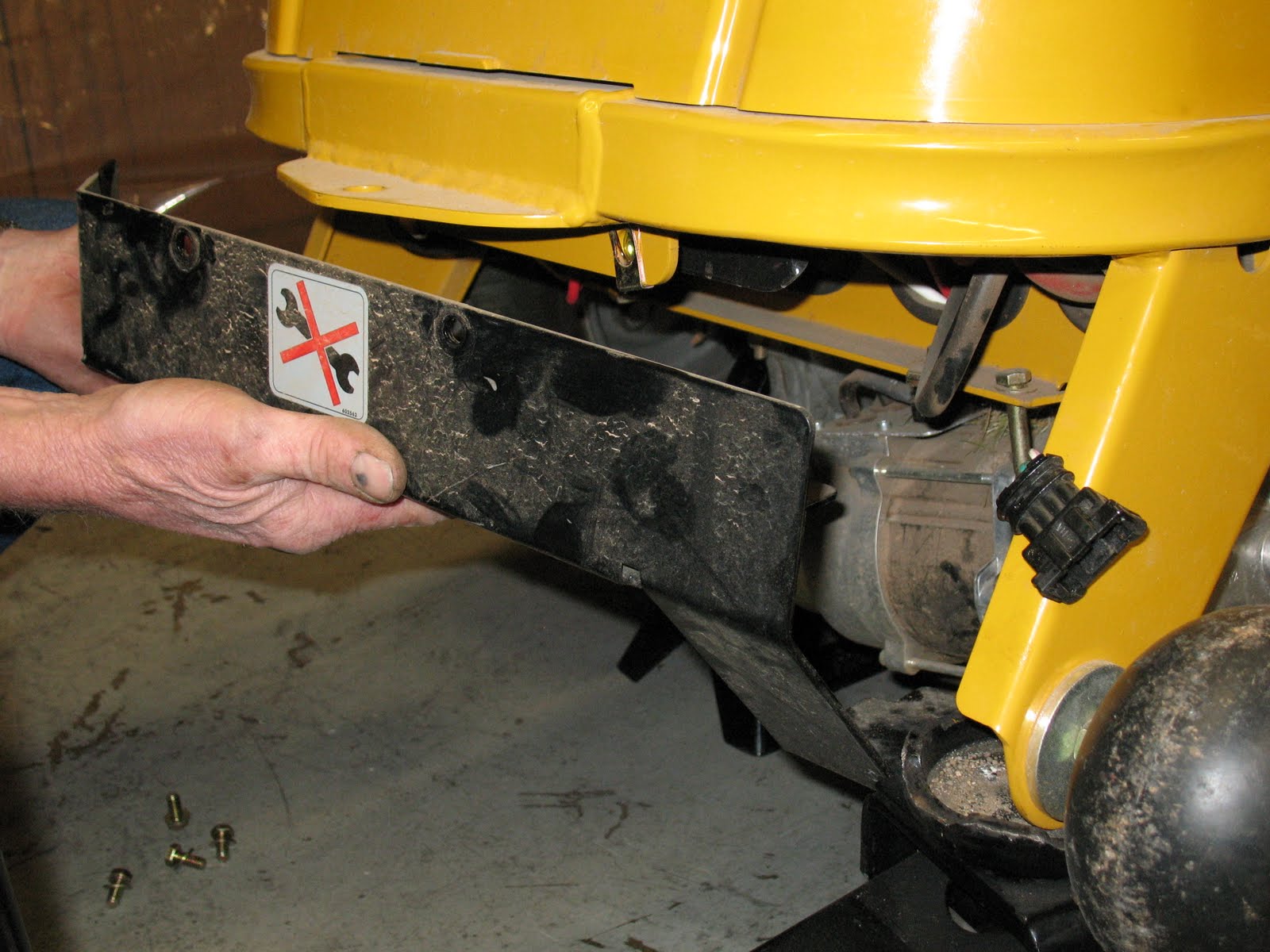
3. Remove the rear electric drive guard.
4. Remove the large gauge electric cables noting their position, as well as the remaining two harness
connections.

5. Illustration below shows an electric drive operating properly as shown on the unit display and the
volt meter.
Safety brake failure
Brake failed in the locked position (we saw on unit with this issue)
- Code 02A13 showing on display
- Verify that the controller or harness is not at fault by installing the electrical park brake release
- If the side in question will not roll easily and the opposite side does, replace the electrical traction drive unit.
My mower works fine all summer, but as cold weather sets in, when I engage the PTO, the blades begin to spin but do not reach full speed and soon cut out with no error showing. This has been happening every year since I have owned the machine. Occasionally, after a number of attempts, the blades will come to full speed and I can mow as normal and restarting after that is no problem, until I try again a week later. Temperature seemto be the problem, but I would like to correct this so that I can use my mower for fall leaf clean-up.
ReplyDelete