The following illustrations show proper battery maintenance procedures
This section has been modified December 2011. The modified information is in a separate section as follows:
1. Never allow the water level to drop below the plates. To avoid this situation check the water level every 3
to 5 cycles. When a pattern appears the water can be checked less and less often. Be sure to use the filler
jug provided with distilled water. Low battery water seems to affect the charger function such as not
allowing the green light to to indicate the charge cycle is complete and as a result the charger will continue
the charge cycle indefinitely.
2. The charger should switch off at 20 hours but we have had chargers that in given situations will not turn the
green light on to indicate the end of a charge cycle and they then will continue charging. In other situations
these same chargers will charge and turn off as they should. If the charger is interrupted in any way while
being connected to the Zeon, for instance a power surge or switching the charger off and then on, the
charger will begin a new complete charge cycle and will probably overcharge the battery pack. To insure
that the battery pack does not get overcharged, remove the charger cable from the Zeon charging
receptical after 20 hours of charge time.
If the Zeon is used withing 30 days do not recharge as long as the display shows 10 bars. If the Zeon is
to be stored longer than 30 days the winter storage harness can be attached. If the storage harness is used
the battery pack can then be charged every 45 days for the 20 hour period including disconnecting the
charger after 20 hours.
3. The battery test procedures listed below are valid and can be used. We have found that batteries may
have a short run time even if the voltage and specific gravity test good. It may be necessary to do a load
test to verify the battery pack is producing a short run time. This can be done with a deep cycle load tester
DO NOT use a cold cranking amp battery tester. The deep cycle test is done over a period of several
hours depending on the battery rating and the capability of the tester. The load test can also be done with
a volt meter attached to the battery pack while mowing. If the test is uninterrupted and the mower is ran at
its capacity, the run time for the battery pack should be _???_ minutes. If the deck turns off at 42
volts or less of battery voltage the controllers are operating as they should. If the voltage is above 42
the batteries may not be the issue.
4. I don't have a good test procedure for the charger, I have not yet had one that failed to charge. Just be
sure to unplug the charger from the machine at or about 20 hours and check the water level.
This is the original section with the charger and battery maintenance procedures.
1. Charge battery pack per the instructions in the owners manual. The hours of charge time varies, the pack
will only be properly charged when the green light is lit as shown. The red light indicates that the charger
has a 110V supply. The amber light indicates the charger is still charging and as long as the amber light is
lit the battery pack may have issues but the charger sees the pack as insufficiently charged.
2. Check the electrolyte level periodically per the owners manual.
3. If electrolyte is not covering the plate, as illustrated below, or if electrolyte is below the fill level provided by
the automatic fill level nozzle, water the cell using distilled water as shown in the 2nd illustration.
4. Shown below is the recommended cell watering container that will automatically fill to the proper level
5. It is recommended that the battery pack be fully charged before the battery pack is watered.
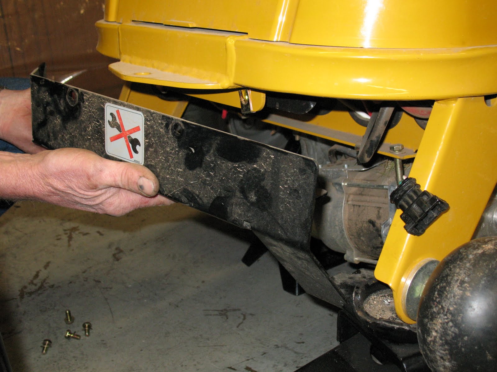
6. Remove the negative post cable as illustrated.
7. Remove the positive and negative battery cable connections and clean all corrosion from the cables and
posts. Illustrations below show a corroded cable and cleaning method. If the corrosion is tight you may
find it necessary to scrape the corrosion off.
8. Tighten all battery connections as illustrated below.
The following illustrations show proper battery testing procedures
If there is an issue of battery's not providing proper voltage or run time, the first step is to charge and clean and tighten the battery pack and connectors as shown above
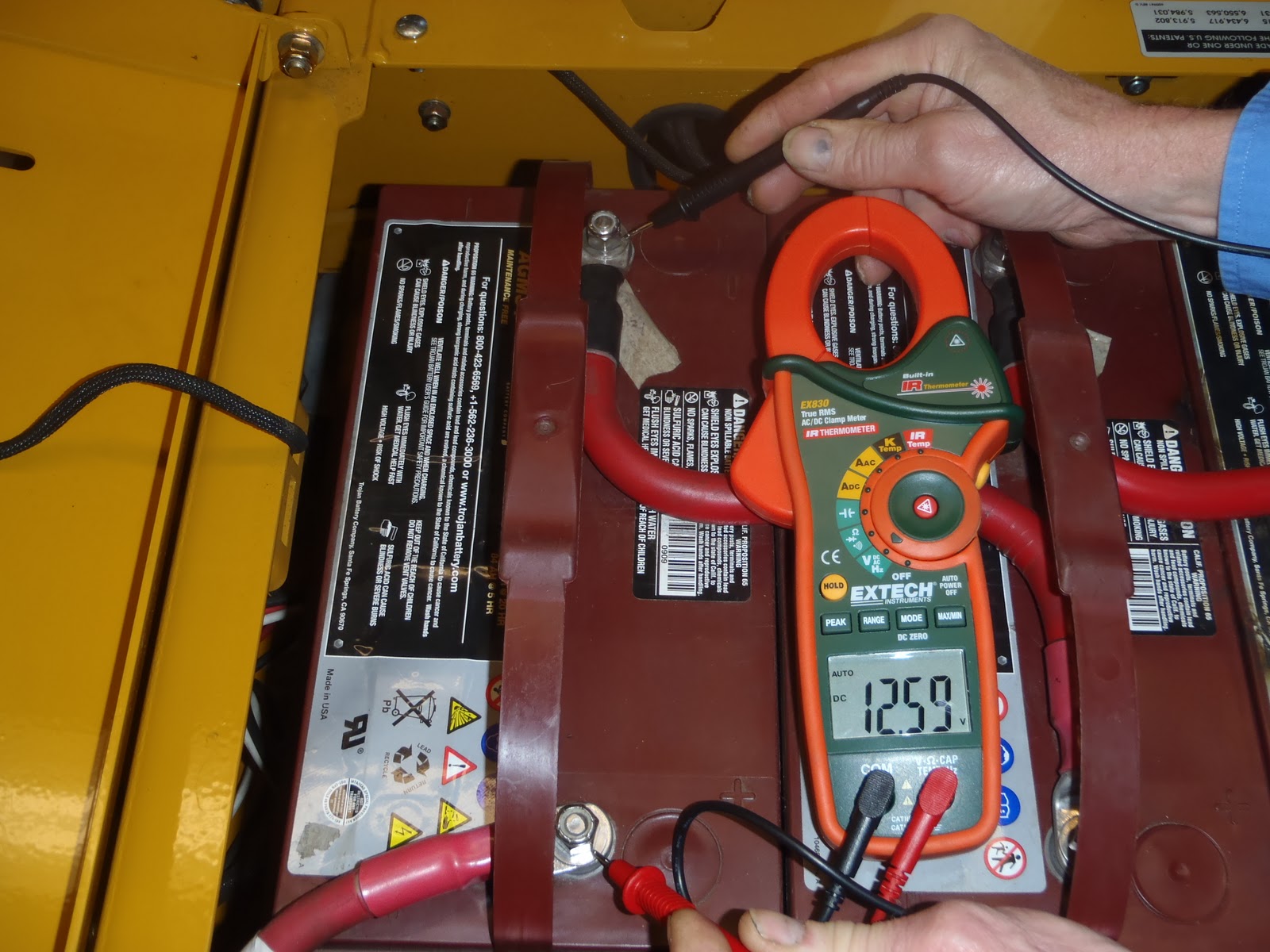
Test battery pack voltage as shown in the first illustration below (ON THE BATTERY POSTS) after 6 hours of rest to allow surface charge to dissipate. Testing on the posts will eliminate battery connection except the large red wires between batteries.
3. A fully charged battery pack will read at least 50.9 volts. The illustration above shows 50.1 volts which is a partial charge.
4. Clean any and all corrosion from the battery cables and terminals if you have not already done so.
5. The red battery connecting cables can remain in place if they are clean.
Notice the difference in test voltage on the number 1 battery when testing on the post compared to
testing a potentially dirty cable.
6. Testing number 2 battery
7. Testing number 3 battery. Notice the voltage increase.
8. Testing number 4 battery. Notice the voltage decrease
9. Test all battery ground connections by probing the positive post and the negative common post at the
bottom of the unit located between the two electric ZT drive trans axle units as illustrated by the following
2 pictures. If the batteries show full charge voltage (12.88), if all cable ends and battery surfaces are
clean, and if the battery electrolyte level is proper, you may want to test the unit performance.
Electrolyte specific gravity test This test will determine if a single cell is below normal.
10. If the battery pack is low or if the unit was tested after the battery voltage test, recharge the battery
pack until the charge lights show as below. This may take as long as 20 hours. Allow the battery to
set idle for 6 hours to allow the surface charge to dissipate before starting the test below.
11. Pull enough electrolyte into the hydrometer to float the internal gauge.
12. Read and record the specific gravity registered on the gauge for each battery cell.
13. Compare your readings to the chart below. There are instructions included with the chart, please
review the instructions to be sure you have done all the steps.
Safety:
Before doing any testing, please follow all the necessary safety precautions. Below are a few safety precautions that will keep personnel safe:
• Always wear protective clothing, gloves, and goggles when handling batteries.
• Do not smoke near batteries.
• Keep sparks, flames and metal objects away from batteries.
• Use a wrench with a rubber handle when making battery connections.
• The electrolyte is a solution of acid and water, so skin contact should be avoided.
• Never add acid to a battery.
Test Procedures:
Below are the tests that should be performed to determine the health of the battery.
Visual Inspection
• Inspect the battery’s case and check for cracks. If a crack is found no testing is
needed since the battery was frozen.
• Check for the overall cleanliness of the battery cover as it can be a good indication of
battery neglect.
• Inspect the battery terminals for corrosion. If corrosion is found on the terminals, they
should be wire-brushed prior to doing any charging or load testing.
Initial Data
• Measure and record the specific gravities of all the cells when the battery first arrives. Pay
special attention to the electrolyte levels and note any cells that have low electrolyte
levels.
• Measure and record the open-circuit-voltages (OCV) of all the batteries
Initial Recharge
• Add distilled water to cells that are very low (near the group) or to cells that have exposed
plates.
• Ensure that all the connections are clean and tight
• If an automatic charger is used, allow the charger to terminate the charge on its own.
Data After Initial Recharge
• Measure and record the specific gravities of all cells 4 to 6 hours after the recharge has
been completed.
• Measure and record the open-circuit-voltages (OCV) of all the batteries.
• An increase in both specific gravities should be observed. The table below can be used to
determine the state-of-charge (SOC) of the batteries.
Table 1 – RE Series
SOC Specific Gravity Open Circuit Voltage
Cell 2V 6V 12V 24V 36V 48V 72 V
100 1.265 2.110 2.110 6.33 12.66 25.32 37.98 50.64 75.96
90 1.246 2.091 2.091 6.27 12.55 25.09 37.64 50.18 75.24
80 1.227 2.072 2.072 6.22 12.43 24.86 37.32 49.73 74.64
70 1.207 2.052 2.052 6.16 12.31 24.62 36.94 49.25 73.92
60 1.187 2.032 2.032 6.10 12.19 24.38 36.58 48.77 73.20
50 1.165 2.010 2.010 6.03 12.06 24.12 36.18 48.24 72.36
40 1.142 1.987 1.987 5.96 11.92 23.84 35.77 47.68 71.52
30 1.119 1.964 1.964 5.89 11.78 23.57 35.35 47.14 70.68
20 1.096 1.941 1.941 5.82 11.65 23.29 34.94 46.58 69.84
10 1.072 1.917 1.917 5.75 11.50 23.00 34.51 46.01 69.00
Table 1
• Should the batteries not reach the values in table 1 after the initial charge, than additional
charging will be required depending on the level of discharge that the batteries were at
when initially received.
• If after the second recharge the battery’s specific gravities do not increase, than it is highly
likely that battery is spent.